 英语
英语 中文简体
中文简体 俄语
俄语 西班牙语
西班牙语
Industry News
Apr 17,2026
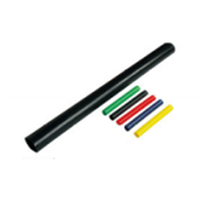
Avoid Failures in 10KV Heat Shrink Intermediate Cable Connector Use.
Failures in medium-voltage cable joints often lead to unplanned outages and costly repairs. Understanding why problems occur with the 10KV Heat Shrink Intermediate Cable Connector helps installation teams reduce these risks.
Failure Pattern: Insulation Damage During Cable Preparation
One frequent cause of premature failure in the 10KV Heat Shrink Intermediate Cable Connector is mechanical damage to the cable insulation during stripping. When an installer cuts the outer sheath or semiconductor layer, the blade may penetrate too deeply, leaving a scratch or gouge in the main insulation. Under operating voltage, this damaged area becomes a weak point where electrical stress concentrates. Over time, partial discharge activity erodes the insulation until a complete breakdown occurs. To prevent this, installers use special stripping tools with depth limiters. After each cut, they inspect the insulation surface under good light. Any visible scratch deeper than a minor surface mark should be addressed before proceeding with joint assembly.
Failure Pattern: Poor Crimping of the Conductor Connector
Another common issue involves the metallic connection between cable conductors inside the 10KV Heat Shrink Intermediate Cable Connector. If the crimping tool does not apply enough pressure, or if the wrong crimping die size is used, the electrical contact resistance becomes higher than intended. This high resistance generates heat when current flows. The heat can transfer to the surrounding insulation layers, accelerating aging. In some cases, the conductor connector loosens over repeated thermal cycles. Installers prevent this by selecting the correct crimping tool and die for the conductor size. After crimping, they check the crimp height with a gauge. Removing any sharp edges or burrs from the crimped area is also necessary, as these points could damage the insulation tube when it shrinks.
Failure Pattern: Moisture Ingress Through Incomplete Sealing
Water penetration is a known risk for any cable joint, and the 10KV Heat Shrink Intermediate Cable Connector is no exception. Moisture can enter at the ends of the outer protective tube if the tube does not fully bond to the cable sheath. It can also enter through pinholes caused by overheating during installation. Once inside, water creates a conductive path or promotes treeing in the insulation. The result is a gradual reduction in breakdown voltage. To avoid this, installers ensure that the cable surface is clean and dry before positioning the outer tube. They apply heat evenly, starting from the middle and moving toward the ends, so that the melted adhesive flows into the gaps. After cooling, a visual check confirms that the tube ends are flush against the cable without visible wrinkles.
Failure Pattern: Incorrect Heating Technique
Applying too much heat or holding the torch in one place too long can damage the 10KV Heat Shrink Intermediate Cable Connector. The material may become brittle, crack, or develop holes. Conversely, insufficient heat leaves the tube partially expanded, creating air gaps. The correct technique involves moving the heat source continuously along and around the tube. The operator watches for the material to become uniformly tight against the cable. A change in surface appearance, such as from matte to glossy, indicates that shrinking is complete. Training sessions for new installers should include practice pieces so they learn to recognize the correct endpoint without guesswork.
Preventive Measures During Site Work
The environment where the 10KV Heat Shrink Intermediate Cable Connector is installed affects the outcome. High humidity or rain introduces moisture that can become trapped under the insulation tubes. Wind can cool the material too quickly, preventing full shrinkage. Installers check weather conditions before starting. If the relative humidity is above a certain level, they either postpone the work or use temporary enclosures with dehumidifiers. They also ensure the cable ends are capped until the moment of joint assembly, keeping dust and moisture away.
Post-Installation Verification
After completing a joint, crews perform acceptance tests to confirm that the 10KV Heat Shrink Intermediate Cable Connector was installed correctly. An insulation resistance test with a suitable megohmmeter gives a baseline reading. A power frequency voltage withstand test applies a higher-than-normal voltage for a short time to check for any weak points. These tests do not guarantee future trouble-free operation, but they catch gross installation errors before the line is energized. Records of test values are kept for comparison during future maintenance.
Related Products


![]()
 +86-15558905711
 +86-15057372736
 [email protected]
 105 Liuxiang Road, Liushi Town, Yueqing City, Wenzhou City, Zhejiang Province, China
